Menu:
Hexacopter
Every time I crashed the ArduCopter I would have to spend a lot of money on shipping and wait several weeks for a tiny replacement part to arrive. I decided I would redesign the frame so I could make replacement parts myself. I planned to use off-the-shelf rods I could cut to length and then connect with 3D printed parts to form the new frame. At the time the 3D printers I had weren't reliable enough for me to start this project, so I put it on hold until I had something I could rely on to make the custom parts. I ended up owning three different 3D printers, but none of them worked well enough to reliably print parts.
A little over six years later I got my Glowforge laser cutter, and decided I would design a frame I could build entirely out of laser cut parts. As I was getting ready to start this project I decided to make sure the flight controller on the old quadcopter still worked. Unfortunately I had trouble connecting to the controller through my computer, and it wasn't responding to the remote control. It is possible it was damaged after moving several times. I was already planning on replacing the motors and ESCs (electronic speed controls) because several of the motors had been damaged, and I had an issue with the quadcopter that I think was due to the ESCs, so this meant I was pretty much starting over from scratch. The only part of the old quadcopter I ended up using in the new one was the remote control and receiver, which were never a part of the original kit anyway.
Since I was starting over with all new parts I decided to build a hexacopter instead of a quadcopter. Partly because they are a little more unique, but also because they can lose one motor and still fly. So I started looking for all of the components I would need: motors, ESCs, propellers, flight controller, power distribution, power management, GPS, etc.
I found some motors I thought would be good for the size of hexacopter I was planning to build, and then selected props and ESCs that were appropriate for the size. The image below shows two of the motors wired to the ESCs.
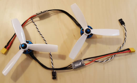
I ended up switching to a slightly different motor than the ones shown above because the model above was discontinued soon after I bought them, and I decided I wanted to be able to buy replacements more easily.
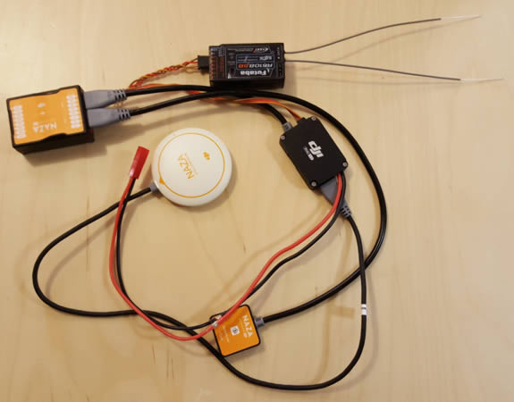
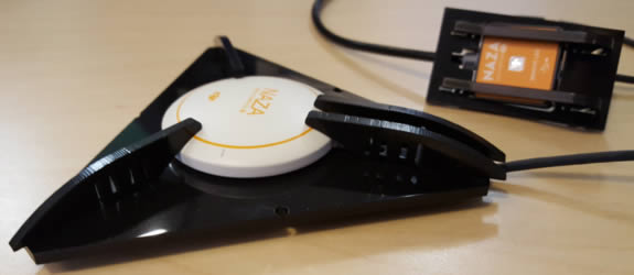
For the flight controller I went with one made by DJI. I decided I didn't want to deal with all of the tweaking that would be required by an open-source controller, and figured the DJI model would probably be more reliable than some of the other cheaper options. The image below shows the DJI flight controller connected to the GPS, power management unit, and USB interface that came as a part of the kit, as well as the receiver.
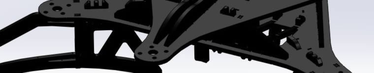
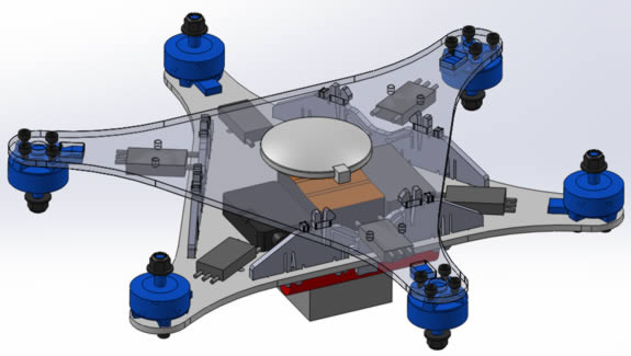
After I received all of the electronic components for the hexacopter I started laying out all of the parts in CAD so I could start designing the frame. The image below shows all of the off-the-shelf parts laid out with the start of what the top and bottom of the frame would look like.
As I was starting to design the frame I ordered several different materials to test. I was pretty sure I would go with acetal, but thought it would be interesting to see how the laser cutter handled cutting each one. I bought sheets of acetal, acrylic, ABS, PETG, and polycarbonate. Acetal and acrylic are known to cut very well on a laser cutter, but the other three are not recommended, mostly due to the amount of smoke they produce.
As a material for the hexacopter, I think acetal, ABS, or polycarbonate would have worked. The impact strength for acrylic is far too low and it would have shattered easily, and PETG wasn't stiff enough. Since ABS and polycarbonate smoke a lot during cutting, I went with acetal for the frame. The image below shows the test parts I made for each of the materials. I made them to get a feel for the stiffness, both by bending the parts, as well as by tightening a motor screw through them to see if they would crack.
I decided early on that I wanted the frame to be entirely snap together. Other than the four screws that hold each motor in place, there isn't any hardware holding the hexacopter together. In the image below you can see the snap features on the pieces that hold the top and bottom of the frame together. Before I started testing the snap features I ran a few simulations to make sure the amount each snap would need to deform wouldn't yield the material.
The design at this stage was starting to get a little larger to accommodate all of the space for wiring after the components were moved closer to their final locations.
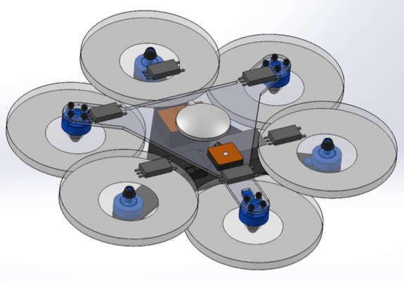
The image below shows the design with the new motors, propellers modeled, and landing feet.
The part I probably spent the most time on was the part that holds the top and bottom of the frame together, mostly because I wanted a way to easily disconnect the top part of the frame. At first I planned on using some type of rotating piece on top that would unlock all of the top snaps at once when it was turned. My first design for this part had the top snaps only on the left side, as shown in the top left corner of the image below. This was done so the rotating feature would unlock both top snaps as it was turned. After thinking about this design a little more I abandoned it because I wasn't sure how I would get something to rotate smoothly with only snap together laser cut parts.
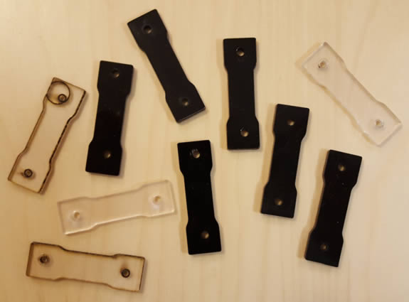
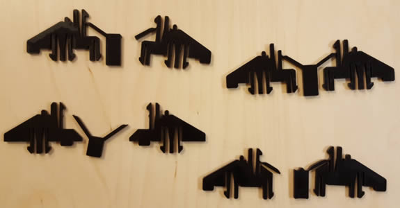
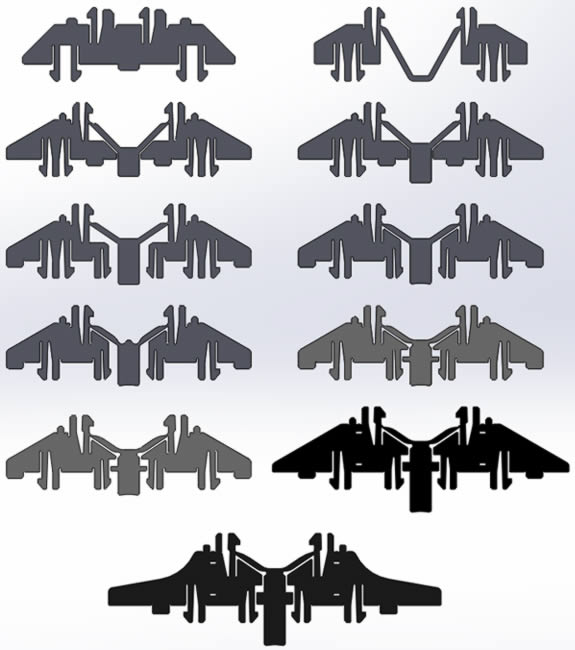
Moving forward I decided to design this part so there would be a button on the bottom, and when this button is pressed it would push the top two snaps apart so they open. There would eventually be 11 designs for this part before I had solved all of the issues and was happy with how it functioned. Designs 1, 3, 4, 5, 6, 7, 8, and 9 are shown in order below.
After each design I would do a stress test that involved pulling on the top and bottom of the frame to see if this part would break. Some of the early failures are shown below.
The video below shows how the quick release button on this part functions.
A screen shot of all 11 designs for this part is shown below.
Many of the changes on the last couple designs were made to address frame stiffness, blade strike issues during hard landings, and to add zip tie holes to attach ESCs.
I ended up making test parts for most of the features that required snap fits before building the entire hexacopter. The image below shows the pieces that hold the GPS in place on the left, and the USB interface on the right.
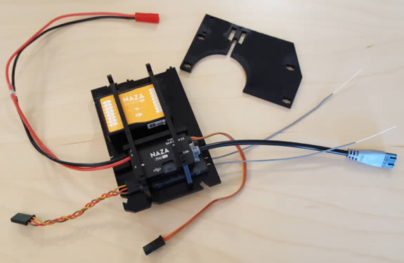
The flight controller, power management unit, and receiver are all contained in the center of the hexacopter. The first test of the parts that hold all of these components together is shown below.
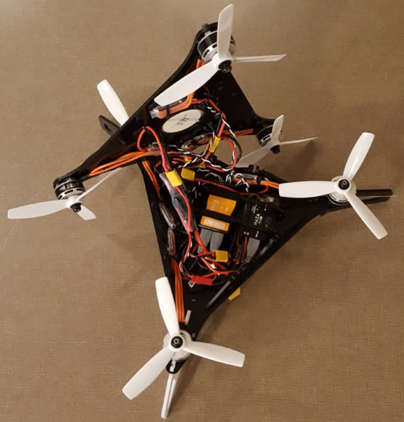
After testing many of the frame components individually I was finally satisfied with the design. The image below shows the design for the first version of the hexacopter I would build.
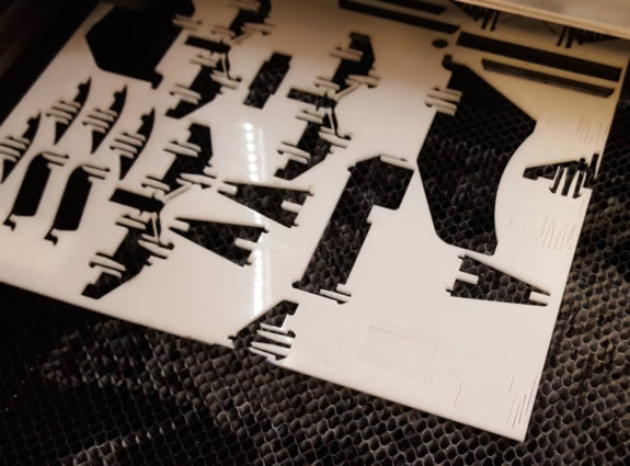
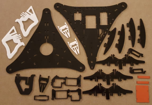
With all of the part testing, I went through quite a few sheets of acetal. The image below shows one of the sheets inside the Glowforge with a bunch of parts cut out to build the hexacopter.
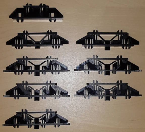
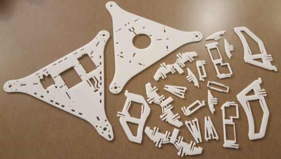
The image below shows all of the parts that make up the first version of the frame.
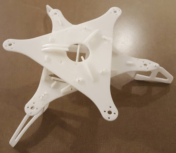
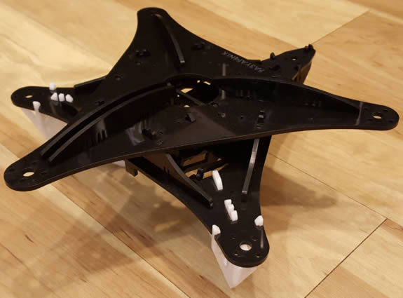
Since everything snaps together, the frame can be built very quickly. The finished frame is shown below. Of course this is without any of the electronic components attached.
The video below shows the first flight of the hexacopter! Unfortunately the first version of the hexacopter oscillated pretty violently. Most of this I was able to reduce by changing the gain settings for the flight controller, but the frame was fairly flexible, and I think that contributed to the problem as well.
For the next version of the design I put a lot of effort into making it stiffer. As you can see in the image below, the parts that hold the GPS in place were extended out toward the motors to stiffen the top. There were also changes to the parts that connect the top and bottom to add stiffness to the bottom of the frame.
I also switched most of the frame to black instead of white. I kept the rear foot white so I would be able to see the orientation of the hexacopter in the air.
The finished cut parts of the second version of the frame are shown below. I also added a couple rubber parts to isolate the flight controller from the frame. I heard that having the flight controller rigidly attached to the frame could have been contributing to the oscillations.
The video below shows the second version of the frame being assembled without the electronic components.
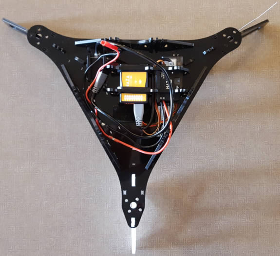
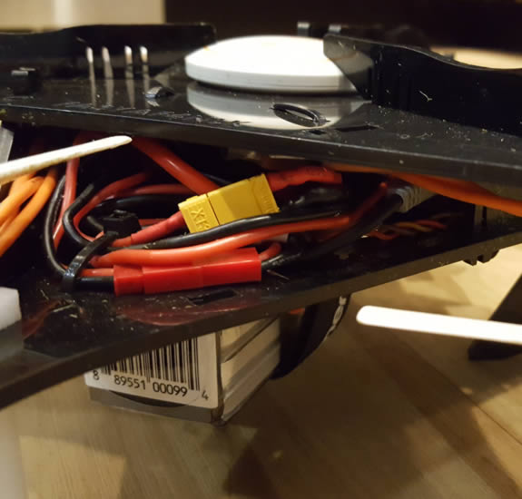
After making sure the frame all fit together, I started adding the electronic components. The image below shows the bottom part of the frame with most of the DJI parts and the receiver attached.
The top part of the frame is shown below with the GPS, motors, and ESCs attached.
After the motors and other components were attached to the bottom part of the frame, the two halves were connected, as shown below.
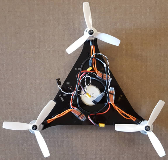
Once all of the wires were tied down, the two parts of the frame snap together to create the finished hexacopter, shown below.
The new version with the changes to the gain settings flew much better. After several flights, and several crashes, I started to learn where the weak points were in the design. I ended up having three crashes before I was forced to make repairs. The first two crashes broke some of the parts that hold the top and bottom together, but overall everything was still okay. Then on the third crash one of the propellers cut through a power cable for the motor, as shown below.
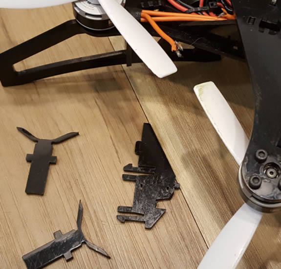
The image below shows an area where half of one of the snap features holding the top and bottom together was left off after a crash.
For the third version of the frame I made some changes to the snap features that hold the top and bottom together to make them more robust. I made additional changes to make the entire frame stiffer, brought the ends of each foot inward so they wouldn't catch the ground as easily during takeoff and landing, and made several other small changes. The frame components in CAD for the third version are shown below.
The video below shows the Glowforge cutting some of the black acetal.
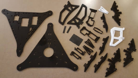
The finished cut parts for the third frame iteration are shown below. The red parts are a thicker silicone rubber used to isolate the flight controller.
The image below shows the assembled frame without the electronic components.
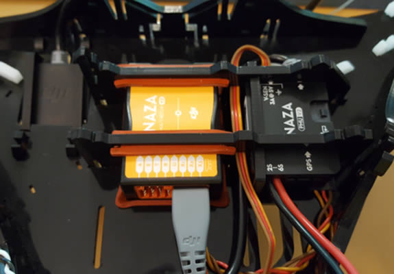
The image below shows the flight controller in the center assembled into the frame with the silicone surrounding it.
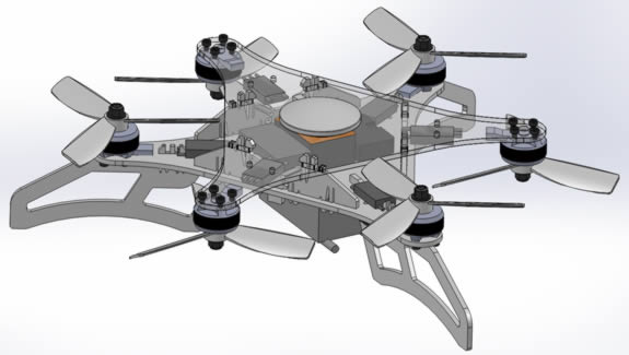
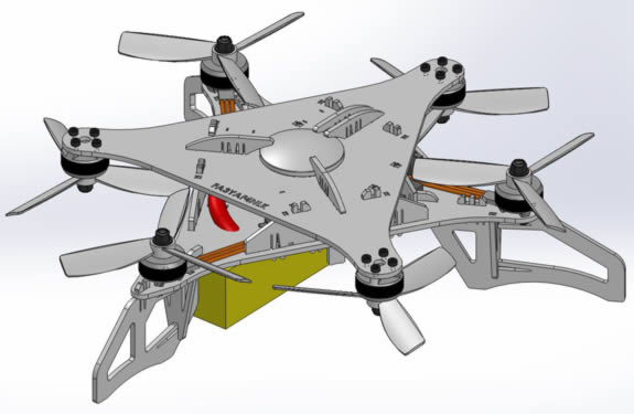
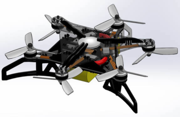
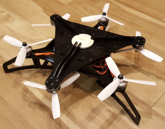
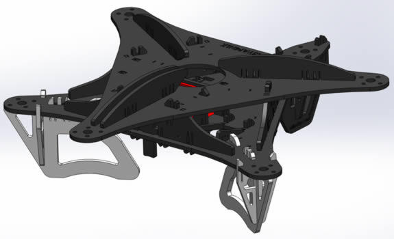
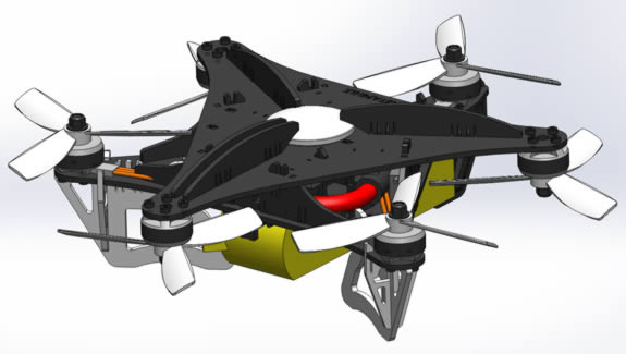
The image below shows the third and final version of the hexacopter in CAD
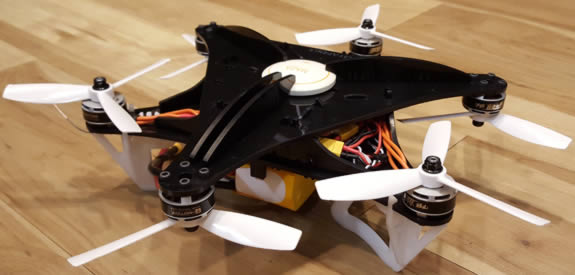
The image below shows the third version of the hexacopter fully assembled.
Once the final design was assembled I decided to test fly it in my apartment, this time without being anchored. This is shown in the video below.
As shown in the video, the hexacopter no longer has the oscillation issue.
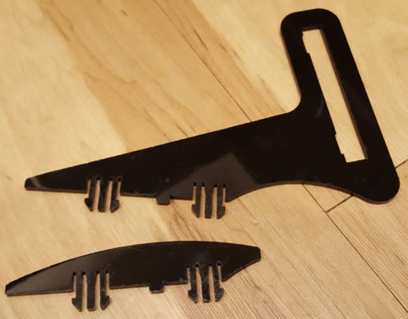
Before taking it for a flight outside I decided to figure out a way to attach a cell phone to the top to film. I designed a part that would replace the front two pieces that hold the GPS in place, but with a cutout I could slide the cell phone through. The new part is shown below next to the original.
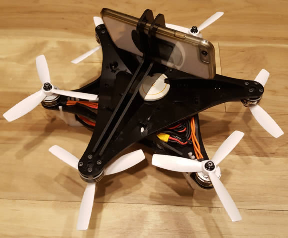
The image below shows the cell phone mount attached with a phone installed.
The video below shows the hexacopter flying outside without the phone mount.
The video below shows a first person view from the hexacopter during a flight. The phone mount doesn't have any features to dampen vibrations which is apparent in the video.
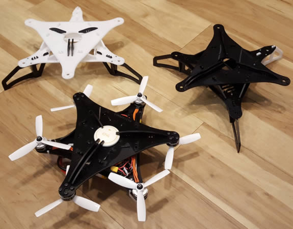
The image below shows all three of the frame designs.
After being satisfied with how the third design handled I decided to call this project finished. I may still make minor changes to the frame in the future if I notice parts that break easily during a crash.
Page created: 2018