Menu:
Truss Analysis
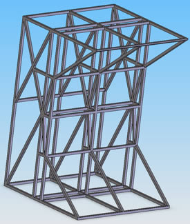
The main project for ME 356 (Machine Design Analysis) was to design a truss made from balsa wood that could hold at least 70 kg. Static analysis was used to develop several base models that met all of the constraints of the project. From these models an FEA (finite element analysis) software package was used to determine the best model. The base model I designed was the model we ended up using, from the original model, slight modifications were made in order to find the best safety factor using the least amount of material (in all I created 25 iterations of this model). The models were designed in SolidWorks and COSMOSXpress was used for the stress analysis. Because we used the basic version of COSMOS, the design had to be modified to allow the loading scenario we would face. The final model is shown below next to the modified design which adds a loading plate.
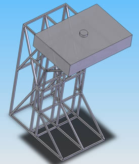
The bottom of the structure was fully constrained so it could not move. The loading plate on the top of the truss was created to represent the shape and location that the actual load would be applied. The stress analysis for this model is shown below next to the actual structure that was created from balsa wood.
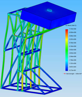
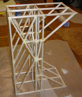
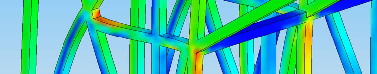
The red parts in the stress analysis image show the areas with the highest stress, these are the areas where the truss was expected to fail. Based on our FEA results, the structure should have been able to support 133 kg. Our real truss was able to support 119 kg. We were able to determine that one of the reasons our truss failed early was because of a small error during construction. One of the three cross sections was built slightly taller than the other two; this would have caused a higher level of stress in that cross section. The point that broke first was one of the areas COSMOS had identified as having a high stress level on the cross section that was not built correctly.
Team members: Dustin Hawkins, Jacob Hiester, Dan Jones
Page created: 2010