Menu:
P3P
ME 495 (Mechanical Engineering Design) was the capstone project class for the BSME program. Most students join either the Formula SAE team or the Human Powered Submarine team. I decided that I wanted to work on a project related to rapid prototyping (RP) so I asked Mark Ganter (the professor for both of the RP classes) if he would act as an adviser for my capstone project. The initial project idea was to create a heated extrusion head for the Fab@Home RP system (which would have essentially turned it into a MakerBot Cupcake CNC). I then assembled a team of students who were interested in working on the project. Just as we were preparing to start, Mark came to us and asked if we would be interested in creating a powder-based printing system instead. This idea sounded a lot more interesting to us because of the added complexity and because (as far as we are aware) a do-it-yourself (DIY) version of a powder-based 3D printer had never been done before.
After the initial design phase of the project was complete, the project was divided into three main groups: the powder group, printer group, and control group. The powder group designed the housing for the machine and the pistons that would move the powder. I worked mainly on the printer group, which was in charge of selecting and modifying the printer so it would work for our needs, as well as designing and building the drive train. The control group was in charge of controlling the movement of the pistons using stepper motors.
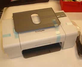
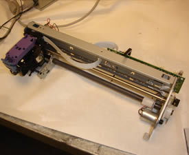
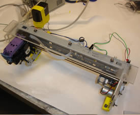
To select a printer, ten different models were taken apart to determine which one would work best; we ended up choosing the Lexmark Z735 because of its simple design. Many of the other models we examined had complicated paper sensing systems that we would have to work around to make the printer do what we wanted (we did not have anyone on the team who was able to modify the printer's firmware so all of our modifications had to be either mechanical or simple electrical changes). Below is an image of the printer we selected next to the stripped down print carriage after the printer was disassembled.
The powder team's first task was to design the system housing. Four versions were designed; an image from SolidWorks of the final design is shown below.
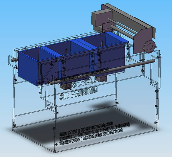
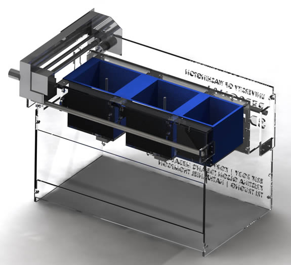
A photorealistic image of the design (which looks very similar to the final machine) is shown below.
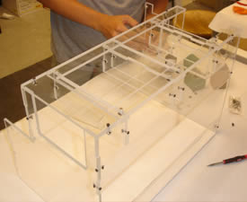
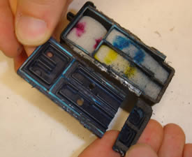
During the project, most of our time was spent in the RP lab trying to get all of the parts to work together the way we needed them to. Below is an image showing the assembly of the machine housing which was made from water jet cut acrylic. Also shown is the print cartridge which was cut open so the ink could be removed and replaced with alcohol which was used as a binder for the powdered sugar we would be printing on.
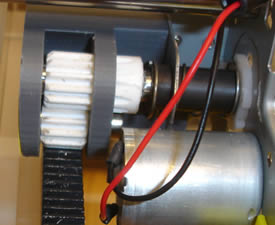
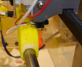
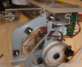
One of the main problems for the printer team was coming up with a way to move the print carriage, which is normally stationary. The roller that feeds paper had to be cut to allow the print heads to get close enough to the powder beds to print. A housing for a gear train was designed that could attach to the printer frame and two gears were cast using a mold created from a gear that had a pitch circle diameter that was the same as the diameter of the paper-feed roller. This was done to make sure the printed images would not be skewed from the printer moving too fast or too slow. Mounts were designed that would bolt to the printer frame to allow it to slide on two rails. The images below show the gear train and one of the rail mounts connected to the printer frame.
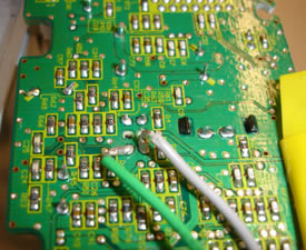
The printer team also had to come up with a way to trick the printer into thinking it had paper when we were ready to start printing, and to make it think there was no longer paper when the print was finished. There is an optical gate on the printer board which is opened when paper is present, and closed when the paper exits the printer. We decided to solder wires onto the board that we could connect to our own switch. The switch was mounted so the printer would move backwards to position itself to print (this would normally be the printer starting to feed paper into the print space), once it was in position (when it thought paper was present) the printer would start to print, once the printer was finished printing the switch would be reset to let the printer know it was done (to make it think the paper had been ejected). The images below show the wires added to the printer board and the switch mounted near one of the rail mounts.
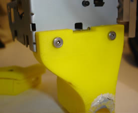
One concern the printer team had was that the torque applied to the frame by the motor (which was acting on one side of the printer) would cause the frame to flex and the rail mount would bind on the side opposite the motor. This happened when the printer was mounted and run for the first time. Because of the time constraints at this point in the project, the problem had to be solved quickly. I ended up using some of the extra parts that had been cut for the machine housing to reinforce the frame. The parts were bolted to the frame and then glued together. This made the frame stiff enough that the mount did not bind on the rail. The images below show the reinforced frame.
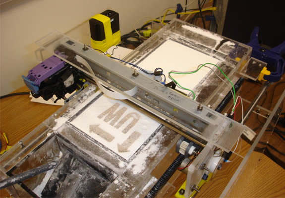
The image below shows the fully assembled machine.
Below is a video showing the printer running through one print cycle.
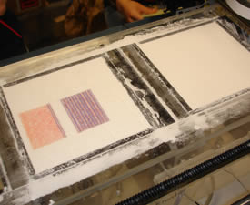
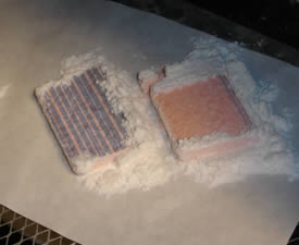
Microsoft Word was used to print the test parts on the printer. Because we did not have a more sophisticated printing method, only 2D extrusions were created. The images below show the first test parts in the printer and after removal. As shown in the second image, the parts started to crumble during removal, this was because we did not have time to determine the correct binder density or layer thickness.
This project was a proof of concept; we were successfully able to show that an inkjet printer could be modified to create a DIY powder-based 3D printer. There are several features we would have liked to have added with more time, but they were left out because they were not requirements for the project. A return mechanism for the printer and a powder spreader would have automated the process (it should be noted that at the beginning of each run our machine was able to correctly align the printer by itself). These features would be easier to implement if we could modify the printer's firmware. We also would have liked additional time to determine the correct printer settings to create stronger parts. A more detailed explanation of the entire project can be found in the file below.
Team members: Kory Koyamatsu, Kristina Olson, Nathaniel Thompson, Tri Truong
Page created: 2010