Menu:
Alarm Clock
On the weekends I sometimes sleep longer than I should if I don't have anything I need to be awake for, so I decided to make an alarm clock that is more difficult to turn off than a normal one. I spent some time thinking about how I could make an alarm clock that I can't easily shut off or reset in the morning, but I also didn't want it to be too frustrating to use. I decided there wouldn't be a snooze button and resetting the alarm or clock would require a pin or screwdriver to push a button inside the case. To turn off the alarm I decided to have two options. One option would be to press two buttons for a predetermined amount of time; if the buttons are released before the time is up, the alarm will turn back on. The second option would involve moving the clock. The clock has an internal battery and two charging docks. There is a reed switch in the clock and a magnet on one of the docks, this dock would be placed in a bathroom or kitchen (wherever the user goes first in the morning after waking up). The alarm is silenced with the buttons on the clock, and deactivated once it is placed in the second dock.
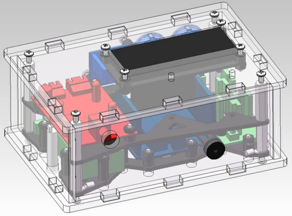
The image below shows the design for the alarm clock.
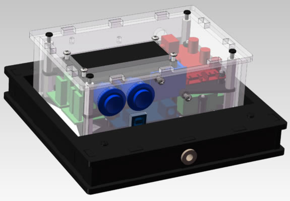
The image below shows the design for the alarm clock sitting in one of the charging docks.
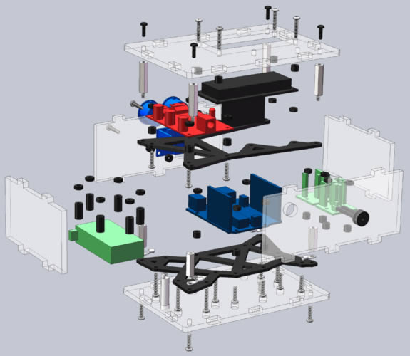
Because this project had quite a few parts that had to fit in a small space, I spent a lot of time going over the design to make sure I would be able to fit everything inside the case, including the wires, and be able to assemble it. Below is an exploded view of the alarm clock.
After I was satisfied with the design I ordered the laser cut parts from Ponoko. The image below shows the laser cut parts and hardware for the alarm clock assembled.

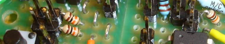
Along with the case design, I had also been working on wiring the electrical components. The image below shows the majority of the electrical components. The power supply is not shown.
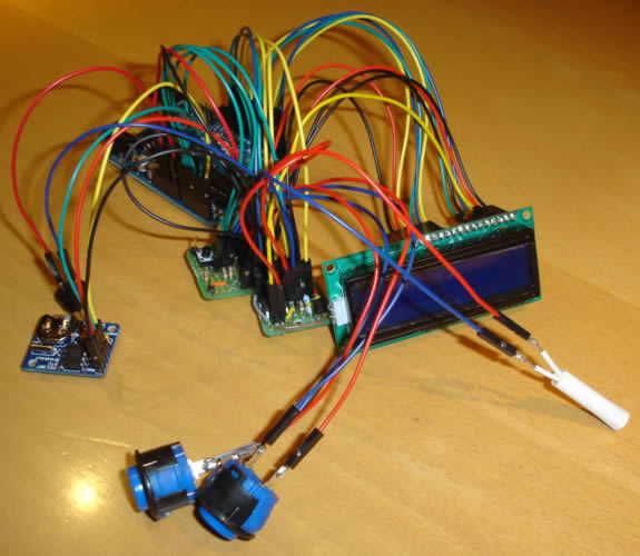
The image above shows an Arduino Uno connected to an LCD, a reed switch, two push buttons, a breakout board with a real time clock, a buzzer, and two other breakout boards. One of the green breakout boards contains a push button and three pull down resistors, the other board has two NPN transistors with resistors, one pull down resistor, and a digital potentiometer.
I started writing the code to test each individual component. I got the display working with the digital potentiometer used to control the contrast. I also got the buzzer to play "wake up" in Morse code.
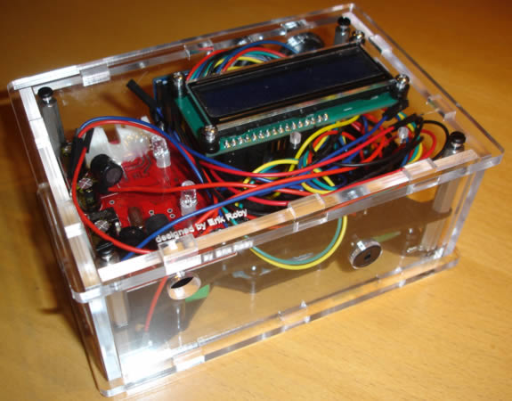
After I had the case parts and the electronics mostly connected, I started to assemble the entire device. The image below shows the case with the electrical components inside.
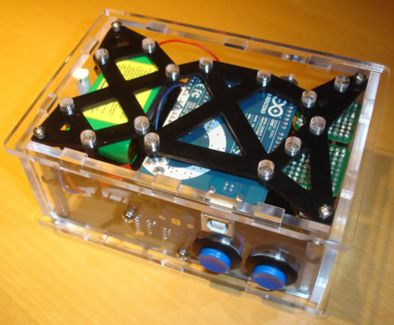
The image below shows the case from the bottom with the components inside.
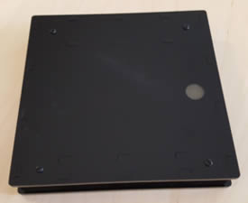
The two images below show one of the charging docks. The image on the left shows the dock from the top side, with two aluminum charge contacts. The steel screws on the bottom of the alarm clock, shown above, are connected to the positive and negative connections on the internal battery charger. I added diodes in between the steel screws and the charger to avoid any damage if the clock was placed in the dock in the wrong direction. The image on the right shows the bottom of the dock. This is the dock that has the magnet for the reed switch to disable the alarm, which is the grey circle on the right side of the image.

The image below shows the alarm clock sitting in the charging dock.

After assembling all of the components, I started to have problems with the battery charger. I had two of them stop working, even though I believe I was applying the correct voltage.
At the time I had a few other projects I was busy with, and after realizing I would need to find a new battery and charger, which would also mean redesigning the case, I decided I was no longer interested enough in the project to continue.
Page created: 2011